
Sinkhole and Void Location Surveys Conducted Nationwide using Ground Penetrating Radar
Email us at geomodel@geomodel.com / 703-777-9788
All surveys are conducted or supervised by Certified Professional Geologists (PG)
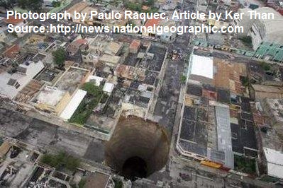
Sinkhole and void location is recommended around and under homes and buildings, over roadways, train tracks, dams, and airport runways, or in any other areas where the subsurface materials are subject to collapse. The best time to have a sinkhole or void location survey conducted, such as a flood damage inspection, is before a collapse, when the subsurface void still exists.
Home Construction Site in Alabama
Sinkhole location surveys are conducted most often in karst limestone areas. However, sinkhole and void location may also be recommended in areas with soft soil, in areas where water or sewer pipes have broken, after a flood to check for flood damage, or where mining or other surface or subsurface disturbance activities have occurred.
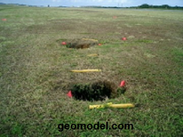
Sinkhole and Void Location Survey Near an Airport Runway
GeoModel, Inc. conducts sinkhole and void location surveys using ground penetrating radar (GPR) and other geophysical methods.
Ground Penetrating Radar Surveys
GeoModel, Inc. is registered with the FCC and uses only FCC-approved GPR equipment
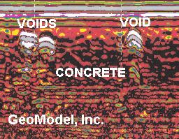
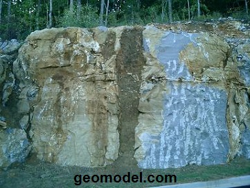
Ground penetrating radar (GPR) produces an underground, cross-sectional, two-dimensional image scan of the soils and subsurface features. The top of the profile shows the ground surface, and the bottom of the image is the deepest extent of the GPR signal in the subsurface.
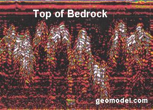
The white and gray areas in the GPR image above indicate karst bedrock pinnacles. The black colors above the bedrock pinnacles indicate generally homogeneous loamy soil, and the red colors below the pinnacles indicate generally horizontal limestone bedrock.
GeoModel, Inc. conducts ground penetrating radar (GPR) surveys using antennas with various frequencies, depending on the depth of investigation.
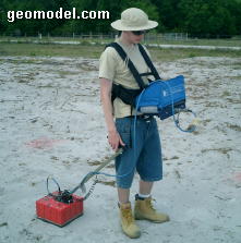
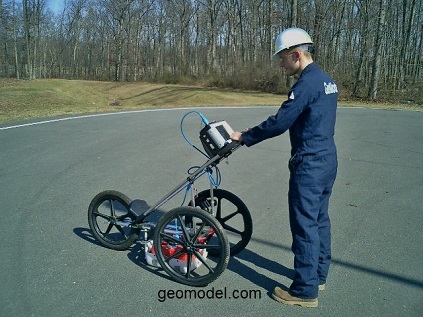
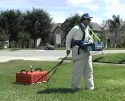
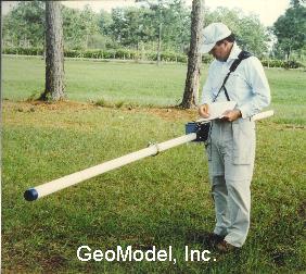
Shallow ground penetrating radar sinkhole location surveys are conducted by one person, hand-towing, cart-moving, or ATV-towing the antenna.
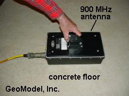
A high frequency antenna (such as the 900-MHz antenna above) can examine very near-surface soils and concrete slabs, up to 3 feet (one meter) thick, at a high resolution. Small voids caused by surface flooding waters, groundwater wash outs, or inadequate placement of concrete can be examined in great detail.
A medium frequency antenna (such as the 400-MHz antenna above) can examine the near-surface sandy soils or limestone bedrock, from 0 to 12 feet (0 to 3.6 meters), in good detail. The ground penetrating radar signal does not go as deep (as little as 1 to 3 feet) in clayey soils or shale rock.
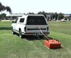
Deep ground penetrating radar sinkhole location surveys are conducted with a low frequency GPR antenna, such as a 200-MHz antenna that can reach depths of up 25 to 35 feet (8 to 11 meters) in sandy soils or limestone bedrock, with less resolution than the 400-MHz antenna. The deep GPR antenna can be hand-towed over the ground surface, but it is usually vehicle- or ATV-towed when possible.
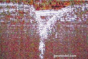
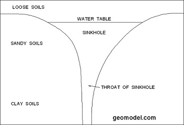
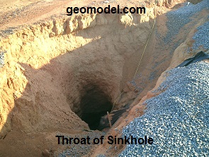
The GPR image on the left above shows the classic cross-sectional profile of a subsurface void or cavity that has not yet collapsed to produce a sinkhole. The top of the Y-shape is the water table and the sides of the Y-shape are the sides of the cavity.
The white feature extending into the lower middle part of the Y-shape is the "throat" of the sinkhole. The throat is the part that extends down into possibly a larger cavity in the soils or limestone bedrock below. We geologists call this extension feature "piping". The drawing on the right above is a labeled schematic of the GPR image on the left.
Electromagnetic Conductivity Surveys
GeoModel, Inc. also uses electromagnetic conductivity to conduct a sinkhole location survey, especially in areas where the soils have significant clay content and the GPR method does not reach the desired depth. Electromagnetic conductivity (or EM) measures the ground conductivity to depths of approximately 20 feet.
The ground conductivity near a potential sinkhole can increase due to an increase in groundwater flow toward the area of subsurface collapse. In areas where the groundwater table is lower than the subsurface void, however, the ground conductivity can be lower because the conductivity of air is lower than subsurface soils or rocks.
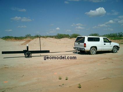
The EM instrument can be hand-carried or vehicle-towed over a potential sinkhole location site, as shown above.
During the EM sinkhole location survey, the EM data is recorded on a field data logger. The data logger is then downloaded to a computer and the data is processed into color contour maps.
Two examples of results of GeoModel, Inc. EM sinkhole location surveys are shown below:
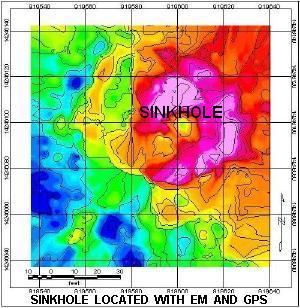
GeoModel Map (above) for a sinkhole located by higher conductivity groundwater in the sinkhole
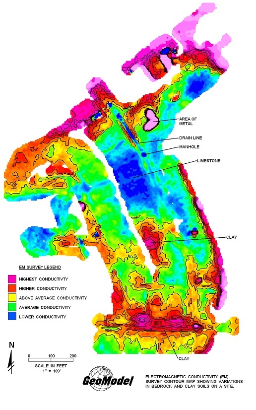
The GeoModel, Inc. color contour map (above) shows areas on the property that have low conductivity (blue and green colors) and high conductivity (orange and red colors). At this site, the groundwater table was low. Therefore, lower conductivity values represented areas where the karst limestone bedrock was closer to the ground surface (blue areas). The higher conductivity values (orange and red) indicated areas where the clay overburden was thicker, or where voids in the limestone bedrock have been filled with clay soil. (The red and pink colors (high conductivity) at the top of the image are caused by proximity to stored construction material that contains metal.)
Void in limestone bedrock has been filled with clay
The image above probably represents a fracture in the limestone bedrock that has been widened by dissolution from groundwater, which was then filled in by surficial clay soils. However, in some cases, the filled void could represent a plugged throat that connects to a larger cavity in the limestone below. In the latter case, if the plug drops down into the cavity, due to either drought conditions or to flooding or high groundwater conditions, then a sinkhole could develop on the ground surface.
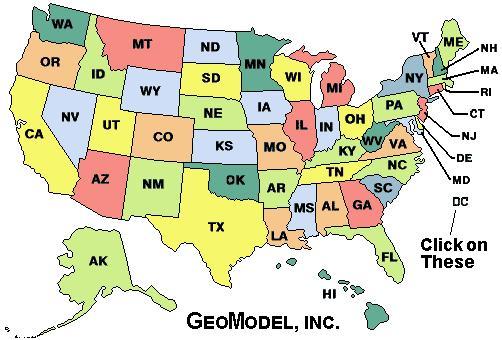
For a ground penetrating radar survey, click on your state below:
e-mail: ![]() geomodel@geomodel.com
geomodel@geomodel.com
 [Back to Top of page][Back to GPR Applications Page]